This post has been edited to clarify some of the details of implementing the polyphase resampler [May 14, 2013].
Time to finish up this look at resampling. In Part 1 we introduced the need for resampling to avoid aliasing in signals, and its implementation by windowed sinc FIR filters. This is a costly operation, however, especially for real-time processing. Let’s consider the case of upsampling-downsampling a 1 second audio signal at a sampling rate of 44.1 kHz and a resampling factor of 4X. Going about this with the brute-force method that we saw in Part 1 would result in first upsampling the signal by 4X. This results in a buffer size that has now grown to be 4 x 44100 = 176,400 that we now have to filter, which will obviously take roughly 4 times as long to compute. And not only once, but twice, because the decimation filter also operates at this sample rate. The way around this is to use polyphase interpolating filters.
A polyphase filter is a set of subfilters where the filter kernel has been split up into a matrix with each row representing a subfilter. The input samples are passed into each subfilter that are then summed together to produce the output. For example, given the impulse response of the filter

we can separate it into two subfilters, E0 and E1
![]()
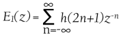
where E0 contains the even-numbered kernel coefficients and E1 contains the odd ones. We can then express H(z) as
![]()
This can of course be extended for any number of subfilters. In fact, the number of subfilters in the polyphase interpolating/decimating filters is exactly the same as the resampling factor. So if we’re upsampling-downsampling by a factor of 4X, we use 4 subfilters. However, we still have the problem of filtering on 4 times the number of samples as a result of the upsampling. Here is where the Noble Identity comes in. It states that for multirate signal processing, filtering before upsampling and filtering after downsampling is equivalent to filtering after upsampling and before downsampling.

Noble Identities for upsampling and downsampling.
When you think about it, it makes sense. Recall that upsampling involves zero-insertion between the existing samples. These 0 values, when passed through the filter, simply evaluate out to 0 and have no effect on the resulting signal, so they are wasted calculations. We are now able to save a lot of computational expense by filtering prior to upsampling the signal, and then filtering after downsampling. In other words, the actual filtering takes place at the original sample rate. The way this works in with the polyphase filter is quite clever: through a commutator switch.
Let’s take the case of decimation first because it’s the easier one to understand. Before the signal’s samples enter the polyphase filter, a commutator selects every Mth sample (M is the decimation factor) to pass into the filter while discarding the rest. The results of each subfilter is summed together to produce the signal, back to its original sample rate and without aliasing components. This is illustrated in the following diagram:

Polyphase decimator with a commutator switch that selects the input.
Interpolation works much the same, but obviously on the other end of the filter. Each input sample from the signal passes through the polyphase filter, but instead of summing together the subfilers, a commutator switch selects the outputs of the subfilters that make up the resulting upsampled signal. Think of it this way: one sample passes into each of the subfilters that then results in L outputs (L being the interpolation factor and the number of subfilters). The following diagram shows this:

Polyphase interpolating filter with a commutator switch that selects the output.
We now have a much more efficient resampling filter. There are other methods that exist as well to implement a resampling filter, including Fast Fourier Transform, which is a fast and efficient way of doing convolution, and would be a preferred method of implementing FIR filters. At lower orders however, straight convolution is just as fast (if not even slightly faster at orders less than 60 or so) than FFT; the huge gain in efficiency really only occurs with a kernel length greater than 80 – 100 or so.
Before concluding, let’s look at some C++ code fragments that implement these two polyphase structures. Previously I had done all the work inside a single method that contained all the for loops to implement the convolution. Since we’re dealing with a polyphase structure, it naturally follows that the code should be refactored into smaller chunks since each filter branch can be throught of as an individual filter.
First, given the prototype filter’s kernel, we break it up into the subfilter branches. The number of subfilters (branches) we need is simply equal to the resampling factor. Each filter branch will then have a length equal to the prototype filter’s kernel length divided by the factor, then +1 to take care of rounding error. i.e.
branch order = (prototype filter kernel length / factor) + 1
The total order of the polyphase structure will then be equal to the branch order x number of branches, which will be larger than the prototype kernel, but any extra elements should be initialized to 0 so they won’t affect the outcome.
The delay line, z, for the interpolator will have a length equal to the branch order. Again, each branch can be thought of as a separate filter. First, here is the decimating resampling code:

Example of decimating resampler code.
As can be seen, calculating each polyphase branch is handled by a separate object with its own method of calculating the subfilter (processDownsample). We index the input signal with variable M, advances at the rate of the resampling factor. The gain adjust can be more or less ignored depending on how the resampling is implemented. In my case, I have precalculated the prototype filter kernels to greatly improve efficiency. However, the interpolation process decreases the level of the signal by an amount equal to the resampling factor in decibels. In other words, if our factor is 3X, we need to amplify the interpolated signal by 3dB. I’ve done this by amplifying the prototype filter kernel so I don’t need to adjust the gain during interpolation. But this means I need to compensate for that in decimation by reducing the level of the signal by the same amount.
Here is the interpolator code:

Example of interpolation resampler code.
As we can see, it’s quite similar to the decimation code, except that the output selector requires an additional for loop to distribute the results of the polyphase branches. Similarly though, it uses the same polyphase filter object to calculate each filter branch, using the delay line as input instead of the input signal directly. Here is the code for the polyphase branches:

Code implementing the polyphase branches.
Again, quite similar, but with a few important differences. The decimation/downsampling MACs the input sample by each kernel value whereas interpolation/upsampling MACs the delay line with the branch kernel.
Hopefully this clears up a bit of confusion regarding the implementation of the polyphase filter. Though this method splits up and divides the tasks of calculating the resampling into various smaller objects than before, it is much easier to understand and maintain.
Resampling, as we have seen, is not a cheap operation, especially if a strong filter is required. However, noticeable aliasing will render any audio unusable, and once it’s in the signal it cannot be removed. Probably the best way to avoid aliasing is to prevent it in the first place by using band-limited oscillators or other methods to keep all frequencies below the Nyquist limit, but this isn’t always possible as I pointed out in Part 1 with ring modulation, distortion effects, etc. There is really no shortage of challenges to deal with in digital audio!

Thanks for this, it’s a great overview. As you said, digital audio is really hard, but your articles make it much clearer than most I’ve read.
Excellent post!, one of the best I’ve found over internet, I’m wondering what size of kernel will be ideal for a 512 sample buffer, I want to do 2X resampling for a distorsion I’m working on.
Thanks!
Thanks very much.
The length of the filter kernel affects the strength of the filter, and thus the amount of attenuation you get in the stopband. It will depend on the distortion algorithm and how much aliasing it has the potential of generating.
The anti-aliasing filter will affect your signal to some extent, so you need to find a balance between that, keeping aliasing away, and execution time.
Maybe to start try something in the range of 40 or so, and then experiment as needed.
Hi Christian, I’m wondering how the index of the z array works in the interpolator algorithm, specifically in the part where z[j+L] is accessed.
Let’s say 4X Upsampling with a 300 tap FIR Filter:
numSubFilters = 4;
totalPolyPhaseOrder = 300;
j will go from 0 to 3.
L will go from 0 to 74 in te for loop.
the boundaries for z array access are:
j = 0;
the z[j+L] index will go from 0 to 74.
j = 1;
the z[j+L] index will go from 1 to 75.
j = 2;
the z[j+L] index will go from 2 to 76.
j = 3;
the z[j+L] index will go from 3 to 77.
Does that make sense?
Is not the size of z array equals to 300?
If that’s the case, why here n goes from 74 to 0 instead of 300 to 0?
for(int n=subFilterOrder-1); n > 0; –n)
{
m_delayLine[n] = m_delayLine[n-1];
}
Thanks for your time and help!.
(Sorry if I’m asking too many questions hehe, I’m trying to figure what is happening exactly there).
Sorry I made a mistake writing m_delayLine[n] = m_delayLine[n-1] instead of z[n] = z[n-1]
Hi Alex,
Yes, you have it right. The mistake, however, is mine. One thing I forgot to mention is that the filter order (number of taps) is always one less than the number of coefficients (size of the kernel) due to the original sample, a0, not being delayed of course. So in your case, that would make the length of the kernel 301. To account for this, we always calculate the order of our polyphase branch/sub-filter as [ order / factor + 1 ].
That will give us our polyphase branch of order 76, not 75 (the extra elements will just be 0), which is also the size of the z array. The mistake above is that it should be z[L], not j+L. The delay line is just multiplied against each branch’s coefficients.
What simplifies it a lot (which I have subsequently done) is to prearrange the FIR kernel in such a way that you just loop through each branch element and multiply by the delay element instead of trying to index the 2D array as above. In other words, the prototype filter kernel is rearranged into the polyphase structure like this:
[ a0 a4 a8 … a300
a1 a5 a9 … a301
a2 a6 a10 … a302
a3 a7 a11 … a303 ]
Since each branch is its own array, it is just multplied by its corresponding z element (z[0] .. z[75]). This is simpler than the 2D indexing above.
As such, I need to edit the post to reflect this when I get the time. 🙂
Thanks for pointing that out. Let me know if you have further questions.
Thanks for your fast the reply Christian!
Ok I pretty much understand what you did, I’ll give it a try, feel free to remove all this replies after the post modification to avoid confusion with the people.
Hi Christian,
I want to down sampling from 48kHz to 8kHz with one channel.. can you please tell me how can i do it. I am very new to this domain.
From 48kHz to 8kHz is down-sampling by a factor of 6, so you would iterate through your audio buffer keeping only every 6th sample and discarding the rest.
i.e. If you have an audio buffer with samples:
0 1 2 3 4 5 6 7 8 9 10 11 12 13 14…
you would keep sample 0 and 6 and 12 and discard the rest.
If your original audio at 48 kHz contains any frequency components above 4 kHz, you have to brick-wall low-pass filter the signal before you downsample, with a cutoff at 4000Hz (or just below it to allow for the transition band) to eliminate any aliasing.
As I’ve outlined in the blog post, this can be accomplished more efficiently all at once with a special filter, but to start off with, do them separately.
Thanks a lot Christian….
I want to do upsampling from 8kHz to 48kHz with one channel.. can you please tell me how can i do it. I am working on realtime data capturing at 20ms.
for 8KHZ i am having 160 samples for 20ms, i want it to upsample to 48kHZ where i need 960 samples for 20ms.
I checked u r interpolating filter code… i am not understanding what is the “kernel[]”…
can you please explain it.
To upsample from 8 to 48kHz is similar to downsampling — every 6th sample you insert 5 0-valued samples. But then you have to interpolate these sample-values to complete the signal. The quality of the interpolation determines the quality of the resampling.
I’ve explained how to use an interpolating low-pass filter in this post.
You also have to low-pass filter the upsampled signal with a cutoff of 24000Hz (again, minus a small transition band) to eliminate aliasing.
The “kernel” you’re referring to is the filter kernel. The interpolating filter is a FIR filter, which is basically a tap-delay with the kernel as the impulse response.
Hi Christian
I work of Multirate Signal processing , i have written many matlab simulations for interpolators and decimators , but i never spent time writing C or C++ implementation ,now i am trying to convert my matlab codes into C codes and your loops for implementing the Decimator and interpolators gave me more insight on how to implement the blocks in C++ or in C .
Like you said we bring in one input and we compute L outputs .
As alex pointed out iam confused with the below lines
we bring in z[0]=input[i];
we compute each arm out put in the for loop
subfilter[j] +=z[j+L] * ProtoFilter[k-j-1] ;
can you kindly confirm the interpolator loop is the final corrected one.
Thanks
Philip
I have updated the post with improved code. I refactored my original design, and this way is much clearer that requires much simpler for loops and indexing (and no kernel flipping!).
There was a mistake in the code you referened. z[j+L] should be z[L]. i.e. The delay line is just MACed with the individual filter branch kernel for each polyphase branch.
As I commented previously, the prototype kernel is decomposed into a matrix, where each row is a branch. The kernel elements are ordered from top to bottom:
[ 0 3 6 …
1 4 7 …
2 5 8 … ]
Hope that helps.
thanks christian ,i was bit confused, thanks for a the wonderful post again, and hope to see another great post from you
hi Christian
Can you kindly confirm the interpolator code is the final updated one .
Thanks
Philip
Thanks. This makes polyphase filters perfectly comprehensible.
On re-reading, I see that you suggested padding the kernels with zero coefficients to make them all the same length. I missed that the first time and had to figure it out the hard way. (-:
The algorithm can be restructured so that the filter easily vectorizes to SSE instructions. Here is how I did it. It actually seems a little simpler: Put N samples in, run the filter, get one sample out.
This file contains bidirectional Unicode text that may be interpreted or compiled differently than what appears below. To review, open the file in an editor that reveals hidden Unicode characters.
Learn more about bidirectional Unicode characters
Decimator
hosted with ❤ by GitHub
Sorry about dumping 300 lines of C++ into your comment section. I thought I was just linking to Github. Stupid WordPress… (-:
No problem. 🙂
I always meant to go back and look at the code to see if I can improve it with intrinsics. I guess you’re relying on auto-vectorization by the compiler because I see no explicit calls to SSE?
It would be interesting to measure the performance to see what kind of gain you get from this.
Yes, I looked at the code generated by the compiler. It is using SSE instructions in the inner loop.
I only wrote a decimator. It measures at about 1.6% of one CPU core in this configuration.
oversample ratio: 4X
decimated sample rate: 44100
sample type: 32 bit float
kernel length: 346 samples
processor: Intel Core i7 Sandy Bridge, 2.3 GHz
I could use less CPU by switching to an FFT, but that would increase the latency. I’m optimizing for end-to-end latency at present, since 1.6% of the CPU is not very much.
And now I’m trying to figure out how to generate good pink noise… White is easy, red (or brown) is easy, pink not so much.
Hi Christian, Nice Article.
I appreciate you taking the time to explain this. I’m currently trying to successfully upsample and interpolate an audio signal from 96000 to 192000. I’m already doing an FFT in order to obtain the 96000 signal. For performance reasons I don’t want to increase my FFT size. My question is this. Would I achieve workable results if I
1. zero stuff the 96000 to upsample it to 192000
2. Interpolate the 0 values using either linear (not preferred) or a cosine interpolation.
3. Apply a Hanning (Cosine Window)
Then overlap and add.
Will the Hanning Window provide an adequate substitute for the described Blackman window? My understanding is that it is still a LPF.
Thanks in advance for any feedback and Happy New Year.
Hi James,
It all really depends on what you intend to do with the signal and what tradeoffs you’re willing to accept between quality and performance cost.
Since you’re at 96k going to 192k, you already have a lot of samples to work with, so linear interpolation may be sufficient if you need to keep performance cost down and are willing to accept a loss in quality. But I would try some others as well, like cubic and hermite and compare.
As for the filtering, you could use a window function, and Hanning would probably be fine since it has almost the same side-lobe roloff as the Blackman window.
It may also be possible to eliminate the filtering all together depending on your signal and the interpolation. If you use a slightly more accurate interpolation, then it may not introduce any audible aliasing, and if your 96k signal is guaranteed to not contain any aliasing frequencies, then you wouldn’t need it.
Hope that helps.
Thanks for the prompt and helpful response Christian. I must say I’m a bit of a follower and I’ve always found your blogs an excellent read. Great suggestions. I’ll have a look at the alternative interpolation implementations.
All my best for the new year.
Thanks! Glad you’re finding it interesting.
Cheers.
Thank you for this nice tutorial about sampling rate conversion.
There are some parts of C++ code in explanations. Is this library available?
No, sorry, it’s not available.
Is there a way to make this linear phase?
for oversample x2, I’ve tried fir filters with even numbers of taps but divisibles by a odd number:
50 taps / 2 = 25 (odd)
But the problem is that these fir filters has a zero as first element in the kernel.
Thank you for the article 🙂
Not with this particular filter kernel. For linear phase to occur, the fir coefficients must be symmetrical about the middle.
Really, any LP filter can be used as an anti-aliasing filter. It depends on how strong you need it to be, and what tradeoffs you’re willing to make between the strength of the filter and computation time.