Tag Archives: LFO

AdVerb: Building a Reverb Plug-In Using Modulating Comb Filters

Some time ago, I began exploring the early reverb algorithms of Schroeder and Moorer, whose work dates back all the way to the 1960s and 70s respectively.  Still their designs and theories inform the making of algorithmic reverbs today.  Recently I took it upon myself to continue experimenting with the Moorer design I left off with in an earlier post.  This resulted in the complete reverb plug-in “AdVerb”, which is available for free in downloads.  Let me share what went into designing and implementing this effect.

One of the foremost challenges in basing a reverb design on Schroeder or Moorer is that it tends to sound a little metallic because with the number of comb filters suggested, the echo density doesn’t build up fast or dense enough.  The all-pass filters in series that come after the comb filter section helps to diffuse the reverb tail, but I found that the delaying all-pass filters added a little metallic sound of their own.  One obvious way of overcoming this is to add more comb filters (today’s computers can certainly handle it).  More importantly, however, the delay times of the comb filters need to be mutually prime so that their frequency responses don’t overlap, which would result in increased beating in the reverb tail.

To arrive at my values for the 8 comb filters I’m using, I wrote a simple little script that calculated the greatest common divisor between all the delay times I chose and made sure that the results were 1.  This required a little bit of tweaking in the numbers, as you can imagine finding 8 coprimes is not as easy as it sounds, especially when trying to keep the range minimal between them.  It’s not as important for the two all-pass filters to be mutually prime because they are in series, not in parallel like the comb filters.

I also discovered, after a number of tests, that the tap delay used to generate the early reflections (based on Moorer’s design) was causing some problems in my sound.  I’m still a bit unsure as to why, though it could be poorly chosen tap delay times or something to do with mixing, but it was enough so that I decided to discard the tap delay network and just focus on comb filters and all-pass filters.  It was then that I took an idea from Dattorro and Frenette who both showed how the use of modulated comb/all-pass filters can help smear the echo density and add warmth to the reverb.  Dattorro is responsible for the well-known plate reverbs that use modulating all-pass filters in series.

The idea behind a modulated delay line is that some oscillator (usually a low-frequency sine wave) modulates the delay value according to a frequency rate and amplitude.  This is actually the basis for chorusing and flanging effects.  In a reverb, however, the values need to be kept very small so that the chorusing effect will not be evident.

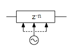
I had fun experimenting with these modulated delay lines, and so I eventually decided to modulate one of the all-pass filters as well and give control of it to the user, which offers a great deal more fun and crazy ways to use this plug-in.  Let’s take a look at the modulated all-pass filter (the modulated comb filter is very similar).  We already know what an all-pass filter looks like, so here’s just the modulated delay line:

Modulated all-pass filter.

Modulated all-pass filter.

The oscillator modulates the value currently in the delay line that we then use to interpolate, resulting in the actual value.  In code it looks like this:

double offset, read_offset, fraction, next;
size_t read_pos;

offset = (delay_length / 2.) * (1. + sin(phase) * depth);
phase += phase_incr;
if (phase > TWO_PI) phase -= TWO_PI;
if (offset > delay_length) offset = delay_length;

read_offset = ((size_t)delay_buffer->p - (size_t)delay_buffer->p_head) / sizeof(double) - offset;
if (read_offset  delay_length) {
    read_offset = read_offset - delay_length;
}

read_pos = (size_t)read_offset;
fraction = read_offset - read_pos;
if (read_pos != delay_length - 1) {
    next = *(delay_buffer->p_head + read_pos + 1);
} else {
    next = *delay_buffer->p_head;
}

return *(delay_buffer->p_head + read_pos) + fraction * (next - *(delay_buffer->p_head + read_pos));

In case that looks a little daunting, we’ll step through the C code (apologies for the pointer arithmetic!).  At the top we calculate the offset using the delay length in samples as our base point.  The following lines are easily seen as incrementing and wrapping the phase of the oscillator as well as capping the offset to the delay length.

The next line calculates the current position in the buffer from the current position pointer, p, and the buffer head, p_head.  This is accomplished by casting the pointer addresses to integral values and dividing by the size of the data type of each buffer element.  The read_offset position will determine where in the delay buffer we read from, so it needs to be clamped to the buffer’s length as well.

The rest is simply linear interpolation (albeit with some pointer arithmetic: delay_buffer->p_head + read_pos + 1 is equivalent to delay_buffer[read_pos + 1]).  Once we have our modulated delay value, we can finish processing the all-pass filter:

delay_val = get_modulated_delay_value(allpass_filter);

// don't write the modulated delay_val into the buffer, only use it for the output sample
*delay_buffer->p = sample_in + (*delay_buffer->p * allpass_filter->g);
sample_out = delay_val - (allpass_filter->g * sample_in);

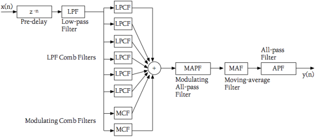
The final topology of the reverb is given below:

Topology of the AdVerb plug-in.

Topology of the AdVerb plug-in.

The pre-delay is implemented by a simple delay line, and the low-pass filters are of the one-pole IIR variety.  Putting the LPFs inside the comb filters’ feedback loops simulates the absorption of energy that sound undergoes as it comes in contact with surfaces and travels through air.  This factor can be controlled with a damping parameter in the plug-in.

The one-pole moving-average filter is there for an extra bit of high frequency roll-off, and I chose it because this particular filter is an FIR type and has linear phase so it won’t add further disturbance to the modulated samples entering it.  The last (normal) all-pass filter in the series serves to add extra diffusion to the reverb tail.

Here are some short sound samples using a selection of presets included in the plug-in:

Piano, “Medium Room” preset

The preceding sample demonstrates a normal reverb setting.  Following are a few samples that demonstrate a couple of subtle and not-so-subtle effects:

Piano, “Make it Vintage” preset

Piano, “Bad Grammar” preset

Flute, “Shimmering Tail” preset

Feel free to get in touch regarding any questions or comments on “AdVerb“.
Shaking it up with Vibrato

Let’s start it off with some music:

Vibrato has always been an essential technique in making music feel more alive, rich, and full of expression.  Whether it is string, wind, or brass players in an orchestra, a singer, or a synthesized waveform in an old 8-bit NES game, vibrato ensures those long notes and phrases connect with us in a more meaningful way by giving them character and shape.

Unlike tremolo (which was the subject of the previous blog entry), vibrato modulates pitch, not amplitude, using an LFO.  When generating a waveform using synthesis, this is a trivial matter as we have direct access to the frequency component.  But with prerecorded audio, the vibrato effect is a achieved through the use of modulated variable delay.  To better understand this, let’s start off by looking at a basic delay effect implemented in C++ code.

The way a simple delay works is by creating a buffer with a length equal to the delay time (making sure to initialize it to contain all zeroes) and then as we process the audio buffer, we transfer each sample from it into the delay buffer while extracting values from the delay buffer and mixing it with the original audio buffer.  Since the delay buffer is initialized to contain all zeroes, the first pass through it will do nothing to the original audio, but upon completing the first pass the delay buffer will contain the samples from the audio that will then be mixed in, creating the delay.  By using a delay time of 0.5 seconds (which would require the delay buffer to contain 22050 samples assuming a sample rate of 44.1kHz), and a ‘depth’ of 45% or so, the following code would generate a single half-second slap-back delay, or echo, at 45% of the original amplitude:

Adapting this code to create a vibrato effect isn’t too complex, but it does require a few steps that might seem a bit hard to grasp at first.  We need to create a variable delay and this requires two pointers to our delay buffer — a writing pointer that will proceed sample by sample as in the basic delay above, and a reading pointer that will be calculated in relation to the writing pointer and modulated by the LFO.  The reading position will almost always fall between buffer positions, so interpolation is required to achieve more accurate output.  With these points considered, the variable delay code becomes:

It was here that I first encountered a big roadblock in writing my vibrato effect.  Upon testing it on a number of soundfiles, I was getting a moderate amount of distortion, or sample noise, in my output.  Having already learned from similar challenges in writing the tremolo effect previously, I was fairly certain this was a new issue I had to tackle.  The test that led me to the source of the problem was using a constant delay time in the code above (no modulation by the sine wave) and that produced a clean output.  From here, I knew the problem had to lie in how I was calculating the offset using the sine wave modulator.  Originally I calculated it like this:

offset = (delay time * sine wave(phase)) * sample rate,

where the phase of the sine wave increments by the value of 2 * pi * freq / SR.  After doing some research (and hard thinking on the matter), it became clear that this was the wrong mathematical operation because multiplying the modulator with the delay time scales it; we want to move “around” it (i.e. vibrato fluctuates pitch by a small amount around a central pitch).  That eventually led me to come up with the following base equation:

offset = (delay time + sine wave(phase) * delay time) * sample rate.

This equation needs a couple more modifications since it isn’t modulating “around” the delay time yet, just adding to it.  A depth modifier needs to be included in here as well so that we can change the intensity of the vibrato effect (by modifying the magnitude of the sine wave).  The final equation then becomes:

offset = (delay time/2 + (sine wave(phase) *depth) * delay time/2) * sample rate,

which simplifies to:

offset = (delay time/2 * (1 + sine wave(phase) * depth)) * sample rate.

This finally created the expected output I was after!  It’s such a great feeling to solve logical programming challenges!  Here is an example of the output with a vibrato rate of 8.6Hz at 32% depth:

Terra’s theme with vibrato rate of 8.6Hz at 32% depth

One other important element to discuss is the actual delay time used to generate the vibrato effect.  I experiemented around with many values before settling on a delay time of 0.004 seconds, which is the value that we “delay around” using the sine wave.  I found as the values got smaller than 0.004 seconds that the sound of the effect degraded, and actually resulted in some sample noise because the delay buffer became so small (nearing as few as only 30 samples).  As the delay time increases, the pitch of the audio begins to vary so much that we actually lose almost all pitch in the original audio.

This is not necessarily a bad thing.  This opens up vibrato to be used as a sound effect rather than purely a musical expression tool.  By setting the delay time to 0.03 seconds for example, the vibrato effect generates an output not unlike a record-scratch or something resembling flanging (which is actually also achieved through the use of variable delay).  See if you can recognize the source music in this sample:

Vibrato effect at 9.0Hz and 75% depth

Of course a more subtle effect is often desired for musical purposes and this is controlled by the depth modifier.  Here is a sample of a more subtle vibrato effect (back to the delay time of 0.004 seconds):

Zelda with vibrato rate of 6.4Hz at a 13% depth

One final thing to mention in regards to applying the vibrato effect onto prerecorded audio is that it can distort the sound somewhat when the audio used is a fully realized composition.  The vibrato is of course being applied on to the entire file (i.e. every instrument, every sound).  A more practical application would be to use vibrato on a single instrument source; a flute for example (please excuse my horrible flute playing):

Flute with vibrato rate of 6.0Hz at a 40% depth

Last, but not least, it is important to consider the implementation and design of the code that applies the effect.  I have continued to code these effects as C++ classes using object-oriented design as it makes the implementation of them very easy and efficient.  For example, calling the effect in the main loop of the program is as trivial as:

Here we can see that first we read sample data in from the soundfile and store it in ‘buffer’.  Then the ‘buffer’ is passed, along with the LFO modulator, into the process that applies the variable delay (vibrato in this case), and this is then written to the output soundfile.  The LFO modulator used for the vibrato is just a new instance of the oscillator class I developed for the tremolo effect previously.  I just initialize a new instance of it for use in the vibrato effect, and done!

This is an example of the benefits of object-oriented design and how adaptable it is.  We’ll be seeing much more of this to come as well.  For example, it would require a few trivial code changes to set up multi-tap delays, each with their own depth, and even to incorporate filters into the delays once I get into developing them.  And finally, allowing the use of envelopes to further shape these effects will be an important step to be taken in the future.  With so many tantalizing possibilities, there’s no stopping now!

Coding some Tremolo

The adventure continues.  This time we occupy the world of tremolo as a digital signal processing effect; also known as amplitude modulation.  My studies into the area of audio programming has progressed quite far I must say, covering the likes of filters and delays (get your math hats ready), reverb, and even plug-in development.  In order to really solidify what I’ve been learning though, I decided to go back and create a program from scratch that will apply tremolo and vibrato to an existing audio file, and that’s where this blog entry comes in.  For now I am just covering the tremolo effect as there is plenty to discuss here on that, while vibrato will be the subject of the next blog entry.

Tremolo in and of itself is pretty straightforward to implement, both on generating signals and on existing soundfiles.  (Vibrato on the other hand is easy enough to apply on to signals being generated, but a bit more complex when it comes to sound input).  Nonetheless, several challenges were met along the way that required a fair amount of research, experimentation and problem solving to overcome, but in doing so I’ve only expanded my knowledge in the area of DSP and audio programming.  I think this is why I enjoy adventure games so much — chasing down solutions and the feeling you get when you solve a problem!

The tremolo effect is simply implemented by multiplying a signal by an LFO (low frequency oscillator).  While LFOs are normally between 0 – 20 Hz, a cap of 10 Hz works well for tremolo.  The other specification we need is depth — the amount of modulation the LFO will apply on to the original signal — specified in percent.  A modulation depth of 100%, for example, will alternate between full signal strength to complete suppression of the signal at the frequency rate of the LFO.  For a more subtle effect, a depth of around 30% or so will result in a much smoother amplitude variance of the signal.  With this information we can develop a mathematical formula for deriving the modulating signal in which we can base our code on.  This is also where I encountered one of my first big challenges.  The formula I used at first (from the book Audio Programming) was:

ModSignal = 1 + DEPTH * sin(w * FREQ)

where w = 2 * pi / samplerate.  This signal, derived from the LFO defined by the sine operation, would be used to modulate the incoming sound signal:

Signal = Signal * ModSignal

This produced the desired tremolo effect quite nicely.  But when the original signal approached full amplitude, overmodulation would occur resulting in a nasty digital distortion.  As can be seen in the above equation for the modulating signal, it will exceed 1 for values of sine > 0.   Essentially this equation is a DC offset, which takes a normally bipolar signal and shifts it up or down.  This is what we want to create the tremolo effect, but after realizing what was causing distortion in the output, I set about finding a new equation to calculate the modulating signal.  After some searching, I found this:

ModSignal = (1 – DEPTH) + DEPTH * (sin(w * FREQ))2

This equation was much better in that it never exceeds 1, so it won’t result in overmodulation of the original signal.  I did however make one personal modification to it; I decided not to square the sine operation after experimenting around with it in the main processing loop.  Ideally we want to perform as few calculations (especially costly ones) within loops as possible.  This is especially important in audio where responsiveness and efficiency are so important in real-time applications.  To compensate for this I scale the DEPTH parameter from a percentage to a range of 0 – 0.5.  From here we can now get into the code.  First, initialization occurs:

Then the main processing loop:

With expandability and flexibility in mind, I began creating my own “oscillator” class which can be seen here:

This is where the power of C++ and object-oriented programming start to show itself.  It affords the programmer much needed flexibility and efficiency in creating objects that can be portable between different programs and functions for future use, and this is definitely important for me as I can utilize these for upcoming plug-ins or standalone audio apps.  Furthermore, by designing it with flexibility in mind, this will allow for the modulation of the modulator so-to-speak.  In other words, we can time-vary the modulation frequency or depth through the use of envelopes or other oscillators.  Values extracted from an envelope or oscillator can be passed into the “oscillator” class which processes and updates its internal data with the proper function calls.  This will allow for anything from ramp ups of the tremolo effect to entirely new and more complex effects derived from amplitude modulation itself!

But now let’s get on to the listening part!  For this demonstration I extracted a short segment of the Great Fairy Fountain theme from the Zelda 25th Anniversary CD release, probably my favorite theme from all of Zelda.

Zelda theme

Here it is after being modulated with a frequency of 4.5 Hz at a depth of 40%:

Tremolo at 4.5 Hz and 40% depth

And for a little more extreme tremolo, we can modulate it at 7.0 Hz at a depth of 85%:

Tremolo at 7.0 Hz and 85% depth

This brings up another challenge that had to be overcome during the development of this program.  Prior to this most of the work I had been studying in the book “Audio Programming” dealt with mono soundfiles.  For this I really wanted to get into handling stereo files and this presented a few problems as I had to learn exactly how to properly process the buffer that holds all the sound data for stereo files.  I am using libsndfile (http://www.mega-nerd.com/libsndfile/) to handle I/O on the actual soundfile being processed and this required me to search around and further adapt my code to work properly with this library.  At one point I was getting very subtle distortion in all of my outputs as well as tremolo rates that were double (or even quadruple) the rates that I had specified.  It took a lot of investigation and trial & error before I discovered the root of the problem lie in how I was handling the stereo files.

In closing off this blog entry, here is a further processing I did on the Zelda sample.  After applying tremolo to it using the program I wrote, I put it through the pitch shifter VST plug-in I implemented to come up with a very eerie result.  ‘Till next time!

Eerie Zelda