We all know how much convolution is used in DSP, and what a significant part it has in making many effects and analysis techniques a reality. Often we hear about FFT, or fast convolution, but in actuality these algorithms are only faster than straight convolution with a kernel length (of the impulse response) greater than around 60 – 64 or so. Anything shorter than that is best handled with normal convolution, which can be implemented using either an input side or output side algorithm.
The input side algorithm is normally the one that we learn first (at least it was for me, and judging from many texts and books on it, it seems to be common). However, the output side algorithm is perhaps slightly easier to code, and we’ll see why later on. For this post I’m going to evaluate the effects each algorithm has on the resulting audio signal because each one could have an advantage in some situations over the other. I’ll also share a little trick that will speed up the convolution process for certain types of filters.
The output side algorithm performs the convolution, as one might expect, from the viewpoint of the output (or the result) of the operation, while the input side algorithm implements convolution from the viewpoint of the input signal. To look at it another way, recall that convolving an input signal with an impulse response results in an output signal that is the length of the input + the length of the impulse response – 1. With the input side algorithm, this “extra” bit of length is appended to the resulting signal, and is probably the easiest one to theoretically grasp. The output side algorithm looks at what points from the input we need in order to get our resulting signal.
The reason why the output side method feels more natural to code is that we often write in terms of the output or result: y(n) = ____ — the output is equal to some kind of expression, for example. Approaching convolution this way requires input samples on the negative side (x[-2], x[-1], etc.), which of course don’t exist. To get around that little problem, one common way is to implement a delay line that contains all zeroes at first, then shifting in the input signal as we go, doing the calculating with the impulse response and the delay line instead of direclty with the input.
I’ve been busy redesigning and overhauling my DSP filter class, which has entailed some experimentation with these two convolution methods on FIR filters. Here we can see visually the difference between them. First up is the output side convolution of a windowed-sinc FIR filter using a Kaiser window of order 162 on a simple triangle wave (using test oscillators is a good way to visually see what’s happening).
I purposely made the filter kernel (impulse response) fairly long so it would illustrate the delay and shift that’s happening at the start of the signal due to the output side algorithm. Compare that with the image of the input side algorithm using exactly the same filter and order.
Huge difference. It’s clearly audible as well in this test signal (samples below). With the output side algorithm there is a clear popping sound as the audio abruptly starts in contrast to the much smoother beginning of the test signal filtered with the input side algorithm.
Here you can hear the difference (to hear it clearly you may have to download the files and listen in an audio editor to avoid the glitchy start of web browser plug-ins):
Triangle wave filtered with output side
Triangle wave filtered with input side
Now to return to the point about the output side method being perhaps a little more natural to code. The little wrinkle we face in implementing the input side algorithm is that with block processing (which is so common in DSP), how do we account for the longer output as a result of the convolution? In many cases we don’t have control over the size of the audio buffers we’re given or have to work with. The solution is to use the overlap-add method.
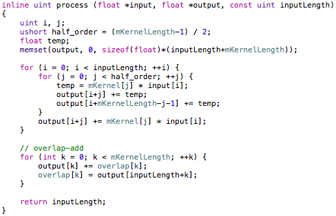
It’s really not more difficult than the output side algorithm. All we have to do is calculate the convolution fully (into our own internal buffer if we have to), save the extra length at the end (which will be equal to the impulse response length), then add that to the start of the next block. Rinse and repeat. Here is C++ code that implements both of these convolution methods.
Don’t worry, I didn’t forget to share the trick I mentioned at the beginning. Many FIR filters have linear phase response, which means that their kernels are symmetrical. That provides us a great opportunity to eliminate extra calculations that aren’t needed. So notice in the above code each ‘j’ loop (the kernel or impulse response loop) only traverses half the kernel length, as the value of input[i] * mKernel[j] is the same as input[i] * mKernel[mKernelLength-j-1]. At the end of the kernel’s loop we calculate the midpoint value.
Again, the calculations involving symmetry is perhaps easier to see in the output side algorithm, because we naturally gravitate towards expressions that result in a single output value. If you work a small convolution problem out on paper, however, it will help you see the input side algorithm and why it works.


